Total Teardown Tutorial
We designed the Voyager to be serviceable in the field. No glue or speciality screws. All you need are simple tools and some patience.
Removing keycaps
Lay the keyboard completely flat on your desk before proceeding, as you will be applying moderate pressure to the unit. Use the included keypuller to remove the caps.
- Use the “wire loop” side of the key puller.
- Place the puller over the keycap and push down.
- The wires will part and “hug” the keycap from below.
- Pull directly up, gently but firmly.
Careful: The low-profile Choc keycaps used on the Voyager have fragile stems — make sure not to twist the keycap or pull at an angle.
Removing keyswitches
Orientation matters when removing a keyswitch. The Voyager has grooves to guide you.
- Use the “tweezers” side of the keypuller.
- Insert the tweezers under the switch, aligning with the grooves in the Voyager case.
- Squeeze the tweezers around the switch.
- Pull up with a smooth upward motion. The keyswitch will come out — victory!
Removing the back cover and PCB
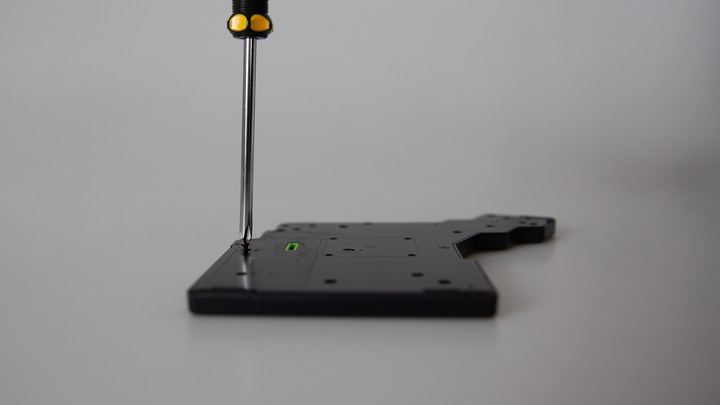
The housing is held together by standard Phillips screws. Note there is no glue.
- Before you begin, make sure you removed all keycaps and keywitches. See Removing Keycaps, and Removing Keyswitches.
- Remove all screws, including the two under the manufacturing label.
- Remove the metal backplate and plastic PCB cover (they go together).
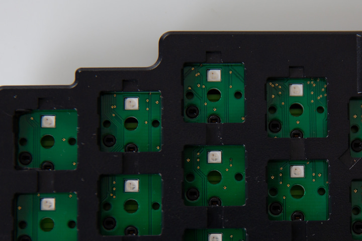
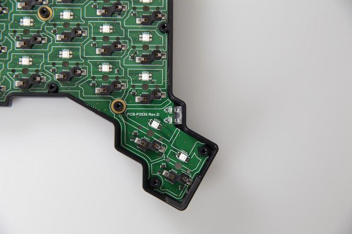
- Gently push the PCB from below, to remove.
Note: There is a small translucent plastic piece used for the layer LEDs near the thumb cluster. It is easy for this piece to fall out or even fly out during this process, and it may be hard to find it again. Go slowly and keep track of this piece as you remove the PCB.
Installing the PCB and closing the unitRemoving the PCB cover
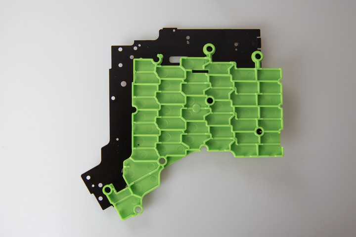
Between the steel backplate and the PCB there’s a layer of carefully molded plastic. This provides support for the keyswitch sockets, as well as insulates the PCB from possible interference via the orientation holes in the backplate.
If you want to examine or replace this cover, you can pop it out. Note that if you do replace it with a DIY solution, whatever solution you create should offer good structural support for the keyswitch sockets.
Putting it back together
Installing the PCB and closing the unit
Slide the sockets into the housing first, and then drop the PCB into place. It should lay perfectly flat. Make sure the small LED cover piece is in position as well before closing the board.
Make sure the plastic PCB cover is snapped onto the backplate. Insert the backplate all the way into the tabs on the side of the case first, which will leave it resting upwards at a slight angle. Then, push the thumb cluster side of the backplate down, closing the board like a book. You will not be able to install the backplate straight on — it must be done like this or it won’t tighten.
With the backplate inserted into the case, you can then begin to tighten the screws. Do not overtighten.
When you’re done, nothing should rattle. Just like new!
Installing keyswitches
Orientation matters when installing a keyswitch:
- Look at the pins on the switch, and look at the socket. Make sure they line up correctly, not upside-down.
- Put the switch over the socket, directly vertically (not at an angle).
- Gently press down until you hear/feel it click into place. This shouldn’t take much force.
If you accidentally bend a pin the switch should still be okay. Just remove the switch, gently straighten the pin, and try again.
Installing keycaps
Carefully locate the keycap on top of the switch so that the pins align with the switch’s “pig snout”. Once you’ve got the alignment right, press down gently.
Do this with the keyboard unplugged, so you don’t end up sending a bunch of random keystrokes to your computer.